TLDR;
This video provides an introduction to electrical fundamentals, starting from basic circuits and atomic science to more complex concepts like Ohm's Law, series and parallel circuits, switches, and safety measures. It explains how electricity works at an atomic level, the roles of conductors and insulators, and the historical progression of electrical discoveries. The video also covers practical applications of electrical principles, including circuit analysis, the use of resistors, and the importance of circuit protection devices.
- Electrical fundamentals are essential for understanding how technology works.
- Electricity involves the flow of electrons and can be understood through water analogies.
- Safety measures, such as circuit breakers and proper wiring, are crucial for preventing electrical hazards.
Introduction [0:00]
The video introduces a series that aims to explain electricity from simple circuits to complex electronics. It encourages viewers to ask "why" and "how" things work, regardless of their current knowledge level. The series promises to provide insights into the fundamentals of electricity.
Part 1 - Pushing Electrons [1:07]
Experts emphasize the importance of understanding electrical fundamentals for anyone working with or interacting with electrical systems. Knowing the basics makes learning advanced concepts easier and prevents frustration. The simplest circuit consists of a power source (battery), a load (light bulb), and conductors (wires).
Atomic Level Science [3:07]
Atoms consist of protons and neutrons in the nucleus, surrounded by electrons. Electrons are negatively charged, and protons are positively charged, creating an electrical attraction that keeps electrons in orbit. Copper atoms have a single valence electron, making them good conductors. Free electrons move between atoms in a chain reaction when pushed by electromotive force (EMF), which is electricity. Conductivity is the property of materials that allows this flow.
A History of Electrical Discoveries [8:30]
Static electricity was first recorded by Thales of Miletus around 500 BC. Alessandro Volta created the first battery in 1799, using chemistry to force electrons to move between copper and zinc. Benjamin Franklin's arbitrary assignment of positive and negative charges led to the concept of conventional current, which flows from positive to negative, though electron flow is actually from negative to positive. Thomas Edison did not invent the light bulb but created the first practical design by using a filament with high resistance.
Why do lightbulbs glow? [14:24]
A light bulb glows because the battery creates an electrical imbalance, causing electrons to flow through the copper cables to the filament. The filament restricts the flow, causing electrons to bump into atom cores, generating heat and light. About 10% of the energy is radiated as light.
Part 2 - Go With The Flow [15:33]
This section uses water analogies to explain electrical concepts. Water pressure is analogous to voltage, and restrictions in a hose are analogous to resistance. The resulting water flow is analogous to current.
Water Analogies [15:37]
The flow of water in a pipe is compared to electricity in a wire. Restrictions in the pipe reduce water flow, similar to how resistance reduces current flow in a circuit. The equation for water flow (flow = pressure/restriction) is analogous to Ohm's Law in electrical circuits.
Ohm’s Law [16:48]
Ohm's Law, published by George Ohm in 1827, establishes the relationship between voltage, current, and resistance: current (I) = voltage (V) / resistance (R). The units are volts for voltage, amperes (amps) for current, and ohms for resistance. Knowing any two parameters allows you to calculate the third.
Real World Measurements [17:37]
Real-world measurements of voltage, current, and resistance are demonstrated using a power supply, voltmeter, ammeter, and multimeter. A multimeter combines the functions of an ammeter, voltmeter, and ohmmeter. Measuring resistance requires the power to be off and the component isolated from the circuit. Light bulbs have low resistance until they heat up.
Theory Into Practice [20:32]
Increasing the voltage to a light bulb increases the current, making it brighter but also generating more heat, which can burn out the filament. When the filament breaks, the resistance becomes infinite, and the current flow stops.
Series Circuits [21:41]
A series circuit has two or more loads connected end-to-end. Adding more loads in series increases the total resistance, decreasing the current flow. Each load takes a portion of the supply voltage. If one light is removed, the entire circuit stops working. Water analogies are used to illustrate how restrictions add up in series.
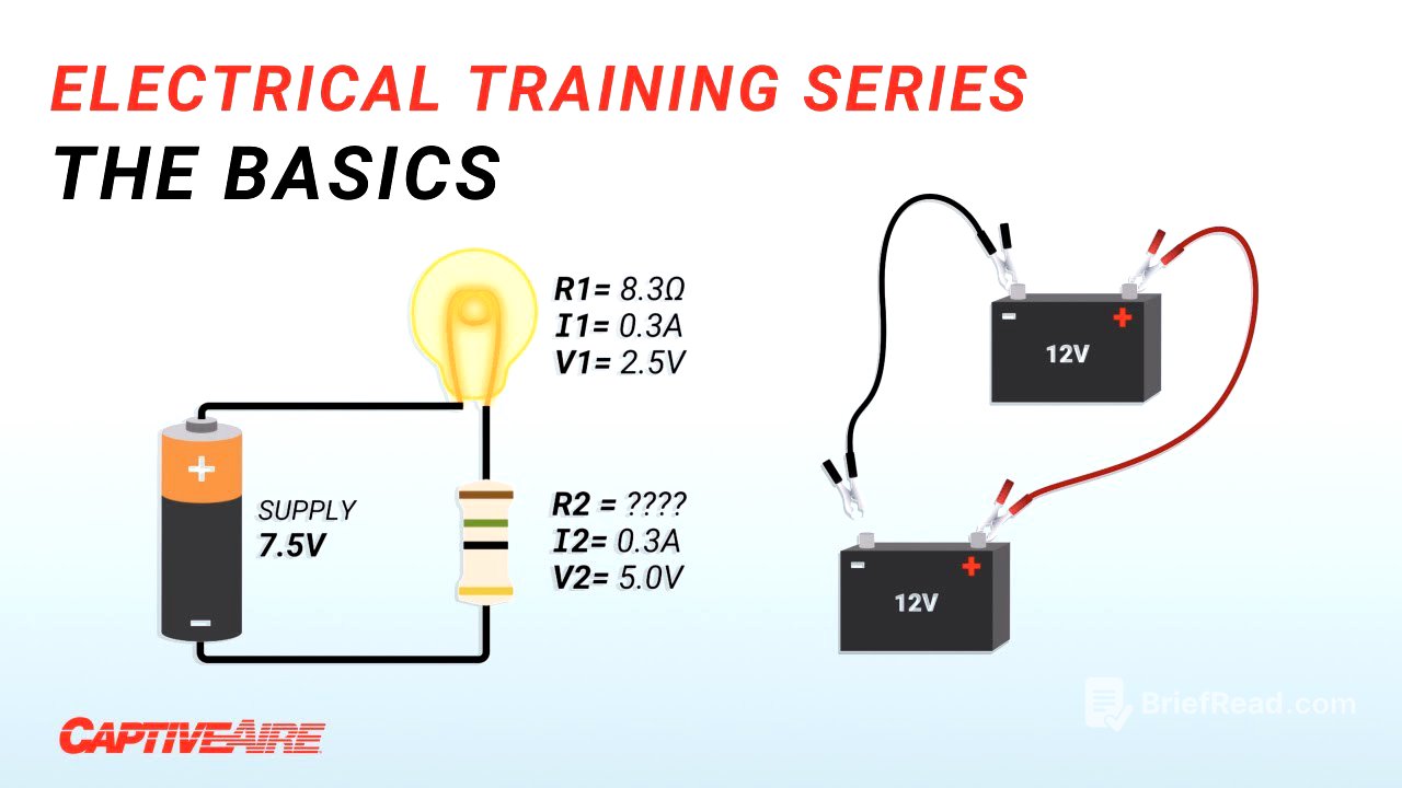
Resistors [24:00]
Resistors are used to drop voltage in a circuit. To use a 2.5-volt light in a 7.5-volt circuit, a resistor can be added in series to drop 5 volts. The size of the resistor is calculated using Ohm's Law. Variable resistors (rheostats) can change the resistance of the circuit, controlling the current flow and brightness of a light.
Parallel Circuits [25:49]
A parallel circuit has loads arranged in parallel loops. Adding more lights in parallel increases the total current draw, decreasing the overall resistance of the circuit. Each light receives the full supply voltage, and if one light goes out, the others stay lit. Water analogies are used to show how more paths decrease overall resistance.
Complex Circuits [29:49]
Series and parallel circuits can be combined into complex circuits. Christmas lights are shown as an example, with series circuits within a parallel circuit. This configuration allows some lights to go out without affecting the entire circuit.
Part 3 - Controlling Nature [30:32]
This section introduces ways to control electricity, starting with switches. Switches have revolutionized electricity by controlling whether electrons can flow through a circuit.
Manual Switches [30:56]
A switch controls whether electrons can flow through a circuit. When the switch is closed, current flows; when open, current stops.
Schematics [31:15]
Engineers and technicians use schematics or circuit diagrams, which are universal symbols representing different components within a circuit, such as batteries, lights, resistors, and switches.
Switch Poles and Throws [31:48]
Switch terminology includes poles (number of separate circuits controlled) and throws (number of possible output connections). Switches can be normally open or normally closed.
Magnetism Basics [32:48]
Like-charged particles repel, and opposites attract due to an electric field. A magnetic field exists when particles are moving. A single moving electron creates a magnetic field around it.
Electromagnets [33:45]
William Sturgeon created the first electromagnet by coiling wire around a nail. This amplifies the magnetic field created by the current flowing through the wire, making the nail a polarized magnet.
Permanent Magnets [34:20]
Permanent magnets work because atoms like iron have asymmetrical magnetic forces due to the number of electrons on the valence shell. When enough of these atoms line up into magnetic domains, they create a usable magnet with a common North and South Pole.
Electromechanical Switches [36:00]
Solenoids, relays, and contactors are electromechanical switches that use an electromagnet to open or close a contact. The circuit used to control the switch is separate from the circuit energizing the load. This allows smaller currents to control larger loads.
Simple Switch Logic [38:03]
Switches can be used to control other switches, creating complex logic. An example is given of a bell that rings continuously due to a mechanism built into the relay circuit.
Part 4 - Basic Safety [39:12]
This section focuses on electrical safety, including circuit breakers, wire gauges, and ground connections.
Why Wires Must be Protected [39:34]
Homes are wired in parallel, so adding more loads increases the current flow through the wires. Wires are rated to handle different amounts of current. Overloading a wire causes it to heat up due to resistance. Thin, long wires are bad at carrying a lot of current.
The American Wire Gauge [40:39]
The American Wire Gauge (AWG) standard specifies the right diameter wire for the expected amount of current. Larger diameter wires have smaller numbers, and small wires have large numbers. The smallest possible wire that can handle the expected load is used for economics.
Circuit Protection Devices [41:40]
Circuit breakers and fuses protect wires and loads from too much current draw. A circuit breaker trips and can be reset, while a fuse goes bad and opens when overloaded.
Slow Trips [41:48]
A slow trip occurs when a circuit breaker trips due to a sustained overload. A thermal element inside the circuit breaker heats up and releases a trip mechanism.
Short Circuits and Fast Trips [42:33]
A short circuit occurs when wires make a connection, bypassing the loads. This creates a very low resistance path, causing almost unlimited current flow. A fast trip occurs when an electromagnetic element inside the circuit breaker triggers a mechanism due to excess current.
Ground in Electrical Devices [43:51]
The ground terminal connects the frame of the appliance to the neutral cable, providing a safety feature. If a wire is shorted to the frame, the current will take the path of least resistance through the ground wire, tripping the circuit breaker.
Bad Connections [45:48]
Bad connections can create resistance in a circuit, generating heat. This can melt insulation and potentially cause a fire. It's important to make proper connections to avoid added resistance.
Conclusion [47:50]
Understanding the fundamental concepts of electricity can make you more effective at interacting with and designing electrical systems safely.