TLDR;
This video is all about the basics of operational amplifiers (op-amps). It explains what an op-amp is, why it's called an operational amplifier, its circuit symbol, open-loop configuration, voltage transfer curve, equivalent circuit, ideal characteristics, and general-purpose op-amp parameters. Key takeaways include understanding the op-amp's function as a differential amplifier, its high gain, saturation behavior, and the differences between ideal and practical op-amps.
- Op-amps amplify the difference between two input signals.
- Ideal op-amps have infinite input impedance, zero output impedance, infinite gain, and infinite bandwidth.
- Practical op-amps have finite values for these parameters and exhibit offset voltage.
What is Operational Amplifier and Why it is known as Operational Amplifier? [0:37]
An operational amplifier, or op-amp, is basically an amplifier that amplifies the input signal. It's called an operational amplifier because, in the early days before digital computers, op-amps were used to perform mathematical functions like addition, subtraction, integration, and differentiation by connecting a few resistors and capacitors. This capability to perform mathematical operations is why it's known as an operational amplifier.
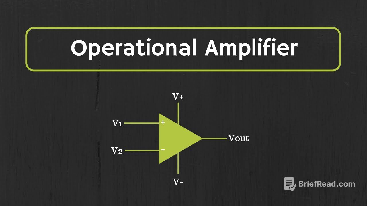
Circuit Symbol of Op-Amp and Op-Amp in the open loop configuration [1:17]
The circuit symbol of an op-amp consists of two inputs (inverting and non-inverting) and one output, and typically uses two power supplies (positive and negative), though some can run on a single supply. The input terminal marked with a positive sign is the non-inverting input, while the one with a negative sign is the inverting input. An op-amp is a differential amplifier with a single output, amplifying the difference between the two input signals (V1 and V2). If the gain of the op-amp is A, the output is A*(V1 - V2). In an open-loop configuration (no feedback from output to input), applying a signal to the non-inverting terminal with the other grounded results in an output of A*V1, where A is the open-loop gain. The output signal's phase is the same as the input signal.
Voltage Transfer Curve of op-amp [5:00]
The voltage transfer curve of an op-amp shows the relationship between the differential input voltage and the output voltage. The slope of the curve represents the gain, typically in the range of 10^5 to 10^6. As the input signal increases, the output voltage increases linearly until it reaches a saturation voltage (+Vsat) which is less than the positive biasing supply. Similarly, for negative input voltages, the output saturates to a negative saturation voltage (-Vsat). In open-loop configuration, even a small input signal can cause the output to saturate to either the positive or negative biasing voltages. This characteristic is useful when using the op-amp as a comparator.
Equivalent Circuit of the Op-amp [7:24]
The equivalent circuit of an op-amp includes an input impedance (Ri), an output impedance (Ro), and a voltage source representing the open-loop gain (A) multiplied by the difference between the input signals (V1 - V2). Ri represents the input impedance of the op-amp, Ro represents the output impedance, and the output voltage is equal to the open-loop gain times the difference between the input signals V1 and V2.
Ideal Op-amp characteristics [7:47]
An ideal op-amp has several key characteristics: infinite input impedance (Ri = ∞), zero output impedance (Ro = 0), infinite bandwidth, and infinite open-loop gain. With infinite input impedance, any input applied is directly applied to the op-amp. With zero output impedance, the output voltage appears directly across the output load. The bandwidth should support all frequencies from 0 Hz to infinity. Additionally, when both input terminals are at zero volts, the output should also be zero. Other ideal characteristics include infinite slew rate (instantaneous response to changes in input) and infinite common-mode rejection ratio (CMRR), meaning it perfectly rejects common input voltages and amplifies only the difference between the inputs.
Characteristics or different parameters of General Purpose Op-Amp (741) [12:00]
Practical op-amps differ from ideal op-amps in several ways. They have finite input impedance (typically in the megaohms range) and non-zero output impedance (typically a few ohms). The open-loop gain is also finite, usually in the range of 10^5 to 10^6. Furthermore, even when the input is zero, a practical op-amp may have a small output voltage, known as the offset voltage, typically in the millivolt range. Different op-amp ICs are optimized for different parameters, such as high slew rate, high open-loop gain, or low offset voltage. The choice of op-amp depends on the specific application and the critical parameters for that application.