TLDR;
This video provides a detailed explanation of capacitance and capacitors, including definitions, formulas, units, and applications. It covers the relationship between charge and potential, the effect of distance and materials on capacitance, and how to calculate capacitance for different configurations. The video also explains how to calculate equivalent capacitance in series and parallel circuits with example problems.
- Capacitance is the ratio of charge gained per potential gained, measured in farads.
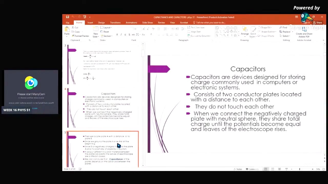
- Capacitors are devices designed for storing charge, commonly used in electronic systems.
- The capacitance of a plate depends on the area of the plates, the distance between them, and the dielectric constant of the material between the plates.
- Capacitors can be connected in series or parallel, each configuration having a different formula for calculating total capacitance.
Introduction to Capacitance and Capacitors [0:25]
The lesson begins with defining capacitance as the ratio of charge gained per potential gained by conductors. This ratio is expressed as C = Q/V, where C is capacitance, Q is charge, and V is potential. The unit of capacitance is the farad (F), equivalent to coulombs per volt. Capacitance is a scalar quantity.
Relationship Between Charge and Potential [2:18]
The video explains the directly proportional relationship between charge gain and potential gain. A graph illustrates this, showing that as charge (Q) doubles or triples, the potential (V) also doubles or triples. The slope of this graph represents the capacitance. The tangent of the angle (theta) formed by the line and the x-axis is equal to Q/V, and therefore also equal to the capacitance (C).
Units of Capacitance and Formulas [7:32]
The commonly used unit for capacitance is the picofarad (pF), which is equivalent to 10^-12 farads. Other units include microfarads (µF, 10^-6 F) and nanofarads (nF, 10^-9 F). For a conductor sphere with radius R and charge Q, the capacitance can be calculated using C = R/q. Various formulas are derived for calculating capacitance (C), charge (Q), and potential (V) based on different given parameters.
Capacitors: Devices for Storing Charge [9:37]
Capacitors are devices designed for storing charge and are commonly used in computers and electronic systems. They consist of two conductor plates separated by a distance. The plates do not touch each other to prevent shocks. When a negatively charged plate is connected to a neutral plate, they share the total charge until their potentials become equal.
Factors Affecting Capacitance [12:01]
The capacitance of a plate depends on the distance between the plates. If an insulator material is placed between the plates, the leaves of an electroscope connected to the plates close slightly. The video presents an illustration of two plates, A and B, separated by a distance D, with an insulator between them. Plate A is positive, and plate B is negative, connected to the ground.
Formula for Capacitance of Parallel Plates [15:56]
The capacitance of a plate depends on the area of the plates (A), the distance (D) between them, and the dielectric constant (ε₀) between the plates. The formula for capacitance is C = ε₀ * A / D. The dielectric constant (ε₀) varies depending on the material, with a value of 8.85 x 10^-12 F/m for a vacuum. Formulas for finding D and A are also derived from the main formula.
Example Problem 1: Calculating Capacitance [17:36]
The first example problem involves calculating the capacitance of a capacitor with dimensions 30 cm by 40 cm and a separation distance of 8 mm. The given values are converted to meters: 30 cm = 0.3 m, 40 cm = 0.4 m, and 8 mm = 0.008 m. The area is calculated as 0.3 m * 0.4 m = 0.12 m². Using the formula C = ε₀ * A / D, the capacitance is calculated.
Example Problem 2: Finding the Amount of Charge Stored [23:40]
The second example problem asks to find the amount of charge stored on a capacitor with a capacitance of 4 x 10^-6 F when connected across a 12-volt battery. Using the formula Q = C * V, the charge is calculated as 4 x 10^-6 F * 12 V = 4.8 x 10^-5 C.
Example Problem 3: Determining the Area of the Plate [26:56]
The third example problem involves determining the area of a capacitor plate if the plate separation is 2.0 x 10^-3 m and the capacitance is exactly 1 F. Using the derived formula A = C * D / ε₀, the area is calculated.
Example Problem 4: Calculating the Voltage of a Battery [29:23]
The fourth example problem asks to calculate the voltage of a battery connected to a parallel plate capacitor with a plate area of 2.0 cm² and a plate separation of 2 mm, if the charge stored on the plates is 4.0 pC. The area is converted to square meters (2.0 x 10^-4 m²) and the separation to meters (0.002 m). The capacitance is calculated first, and then the voltage is found using V = Q / C.
Example Problem 5: Determining the Plate Separation Distance [34:01]
The fifth example problem involves determining the plate separation distance for a parallel plate capacitor with a plate area of 2.0 m² and a capacitance of 7.9 nF. Using the formula D = ε₀ * A / C, the plate separation distance is calculated.
Capacitors in Series and Parallel: Introduction [36:21]
The video transitions to discussing systems with multiple capacitors and how to find their equivalent capacitance. Capacitors can be connected in series or parallel. For capacitors in parallel, the total charge is the sum of the individual charges, and the equivalent capacitance is the sum of the individual capacitances (Ceq = C1 + C2 + C3 + ...).
Capacitors in Series: Explanation and Formula [40:07]
For capacitors in series, each capacitor has the same charge. The total voltage is the sum of the individual voltages. The formula for the equivalent capacitance in series is 1/Ceq = 1/C1 + 1/C2 + 1/C3 + ....
Example Problem 6: Calculating Equivalent Capacitance [44:07]
The sixth example problem involves calculating the equivalent capacitance between points A and B in a circuit where C1 = 2C, C2 = C, and C3 = C. C1 and C2 are in parallel, and their result is in series with C3. The equivalent capacitance for the parallel combination of C1 and C2 is C12 = 3C. The equivalent capacitance for the entire circuit is then calculated using the series formula.
Example Problem 7: Series and Parallel Connections [51:28]
The seventh example problem asks to determine the effective capacitance for C1 = 10 F and C2 = 5 F connected in series and in parallel. For the series connection, the equivalent capacitance is calculated using the series formula. For the parallel connection, the equivalent capacitance is simply the sum of the two capacitances.
Example Problem 8: Complex Circuit Analysis [55:03]
The final example problem involves a more complex circuit with C1 = 60 µF, C2 = 20 µF, C3 = 9 µF, and C4 = 12 µF. The potential difference between points A and B is 120 V. The task is to find the charge of the second capacitor. The problem is solved step-by-step, first finding the equivalent capacitance of C1 and C2 in series, then combining that result with C3 in parallel, and finally combining that result with C4 in series to find the overall equivalent capacitance. The charge on the second capacitor is then calculated.