TLDR;
This video provides an introduction to logic gates, fundamental components in control systems and electronic engineering. It explains binary numbers (0 and 1) and their role in determining conditions within circuits. The video covers basic logic gates (AND, OR, NOT) and how to determine the nature of input variables using truth tables. It also provides real-world examples of AND and OR gates in electronic circuits and industrial automation.
- Logic gates process logic into binary values (0 or 1).
- Truth tables are used to determine the nature of input variables.
- AND, OR, and NOT are basic logic gates with specific functions and applications.
Introduction to Logic Gates [0:00]
The video introduces logic gates, which are commonly used in control systems like PLCs and electronic engineering. Logic gates operate using binary numbers, 0 and 1, which define conditions in control system circuits. The value of a binary number is determined by the position of 0s and 1s; in logic, 1 represents "yes" and 0 represents "no". Logic gates process logic into a value, having one output (0 or 1) and one or more inputs (each 0 or 1). The output depends on the type of logic gate and the input variables.
Truth Tables Explained [1:51]
To determine the nature of input variables, a truth table is used, consisting of input and output columns. For a logic gate with one input (A) and one output (Y), the truth table lists possible values of A (0 or 1) and the corresponding output. For two inputs (A and B), the table includes all combinations of A and B (00, 01, 10, 11). The number of input combinations is determined by the formula 2^n, where n is the number of inputs. For example, with 3 inputs (A, B, C), there are 2^3 = 8 combinations.
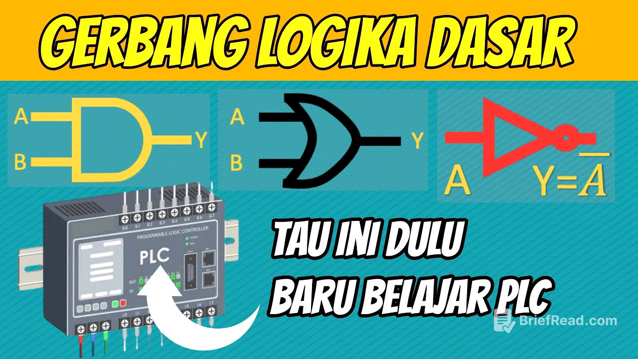
AND Logic Gate [5:35]
The AND logic gate has two or more inputs and one output. Its algebraic expression is Y = A * B (or A.B). For example:
- If inputs A and B are 0 and 0, the output Y is 0 (0 * 0 = 0).
- If inputs A and B are 0 and 1, the output Y is 0 (0 * 1 = 0).
- If inputs A and B are 1 and 0, the output Y is 0 (1 * 0 = 0).
- If inputs A and B are 1 and 1, the output Y is 1 (1 * 1 = 1). In an electronic circuit, an AND gate can be represented by a circuit with two push buttons (A and B) in series. The lamp will only light up (Y = 1) if both buttons are pressed (A = 1 and B = 1). In industrial automation, a press machine uses two push buttons for safety, requiring both to be pressed simultaneously to activate the machine.
OR Logic Gate [8:10]
The OR logic gate has two or more inputs and one output. Its Boolean algebra expression is Y = A + B.
- If inputs A and B are 0 and 0, the output Y is 0 (0 + 0 = 0).
- If inputs A and B are 0 and 1, the output Y is 1 (0 + 1 = 1).
- If inputs A and B are 1 and 0, the output Y is 1 (1 + 0 = 1).
- If inputs A and B are 1 and 1, the output Y is 1 (1 + 1 = 1). In industrial automation, an OR gate can be used to control a motor from two different locations. Pressing the push button in either location will start the motor.
NOT Logic Gate [9:49]
The NOT logic gate has one input and one output. The output Y is the inverse of the input A, denoted as Y = Ā. If A is 0, then Y is 1. If A is 1, then Y is 0. This gate is commonly used in electronic circuits to invert signals. If the signal A is 0, then the signal Y is 1, and vice versa. The video concludes by mentioning that derived logic gates will be explained in the next video.