TLDR;
This video is all about Silicon Controlled Rectifiers (SCRs). It covers what SCRs are, their structure, how they work in different modes, and their static V-I characteristics. Key takeaways include understanding the three modes of operation (reverse blocking, forward blocking, and forward conduction), the importance of latching and holding currents, and how the gate terminal controls the SCR's turn-on process.
- SCR stands for Silicon Controlled Rectifier and is also known as a thyristor.
- SCRs have three modes of operation: reverse blocking, forward blocking, and forward conduction.
- Latching current is the minimum current required to turn on the SCR, while holding current is the current below which the SCR turns off.
Introduction to SCR [0:09]
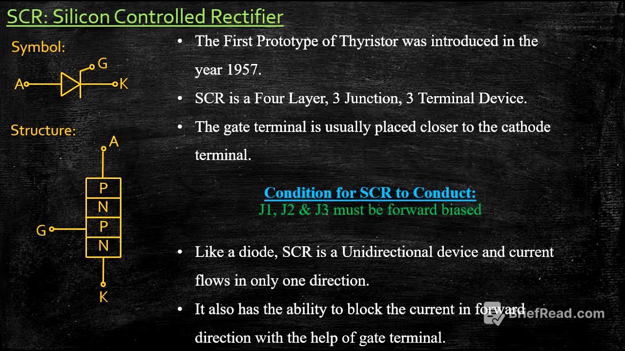
The video begins with an introduction to SCRs, explaining that SCR stands for Silicon Controlled Rectifier. The term "silicon" indicates the material used in manufacturing the device. The word "controlled" refers to the gate terminal, which is used to control the device. SCRs are commonly used in rectifier applications and high-voltage DC applications. They are also known as thyristors, belonging to the thyristor family. The first prototype was introduced in 1957, aiming to combine the properties of diodes and transistors with added control.
SCR Structure and Key Points [2:19]
The discussion moves to the basic structure of an SCR, which includes three terminals: anode, cathode, and gate. It has four layers (P-N-P-N) and three junctions (J1, J2, J3). The gate terminal is placed closer to the cathode to reduce wire length. A key point is that for the SCR to turn on, all three junctions (J1, J2, J3) must be forward biased, allowing current to flow from cathode to anode. Like a diode, an SCR is a unidirectional device, but it can also block current in the forward direction using the gate terminal.
Modes of Operation: Reverse Blocking Mode [5:10]
The video explains the three modes of operation, starting with the reverse blocking mode. In this mode, the anode is connected to the negative terminal and the cathode to the positive terminal, with the gate open (no connection). Junctions J1 and J3 are reverse biased, while J2 is forward biased. The SCR does not conduct and acts as an open circuit. A small reverse leakage current flows due to minority charge carriers. If the reverse voltage exceeds the reverse breakover voltage (VBO), the device can be permanently damaged. Applying a gate voltage in this mode is not useful and can cause power losses.
Modes of Operation: Forward Blocking Mode [9:32]
In forward blocking mode, the anode is connected to the positive terminal and the cathode to the negative terminal, with the gate open. Junctions J1 and J3 are forward biased, while J2 is reverse biased. Again, the SCR remains in the off state and acts as an open circuit, with a small forward leakage current flowing. If the forward voltage (VAK) exceeds the forward breakover voltage (VBO), avalanche breakdown occurs at junction J2, causing the SCR to start conducting. However, this method of triggering is not preferred as it can lead to dangerously high current levels.
Modes of Operation: Forward Conduction Mode [12:42]
In forward conduction mode, the anode is connected to the positive terminal and the cathode to the negative terminal, but now a gate voltage is applied. This forward biases all three junctions (J1, J2, J3), causing the SCR to turn on and conduct. The gate terminal allows control over the turn-on process. Once the SCR starts conducting, the gate has no further control, and the gate supply can be removed. It's important to ensure the anode current reaches the latching current before removing the gate supply. The SCR can be turned off by applying a reverse voltage, reducing the anode current below the holding current. Latching current is associated with turn-on, while holding current is associated with turn-off, and latching current is always greater than holding current.
Static V-I Characteristics of SCR [16:23]
The video concludes with an analysis of the static V-I characteristics of the SCR, which is a plot of anode current versus anode-cathode voltage. Initially, a small forward leakage current flows in the forward blocking mode. As the voltage increases, the current rapidly increases at the latching current point, transitioning to the forward conduction mode. Below the latching current, the holding current is the minimum current to turn the SCR off. Different gate currents (IG1, IG2, IG3) affect the transition from forward blocking to forward conduction. In the reverse region, the characteristics are similar to a diode, with the current abruptly increasing at the reverse breakdown voltage (VBR), potentially damaging the device. The static V-I characteristics are derived from the modes of operation, providing a comprehensive understanding of the SCR's behavior.