TLDR;
This video by All About Electronics explains the half-wave rectifier, a circuit that converts AC voltage into pulsating DC voltage by allowing only one half of the AC waveform to pass through. It discusses the circuit's working principle, key parameters like average value, RMS value, peak inverse voltage (PIV), and ripple factor. The video also covers how to reduce ripple using a capacitor filter, the efficiency of the rectifier, and its applications, particularly in AC to DC conversion and signal demodulation.
- Half-wave rectifiers convert AC to pulsating DC by passing only one half-cycle of the input waveform.
- Key parameters include average value (Vm/π), RMS value (Vm/2), PIV (Vm), and a ripple factor of 1.21.
- A capacitor filter can reduce ripple, but the efficiency of a half-wave rectifier is relatively low (40.6%).
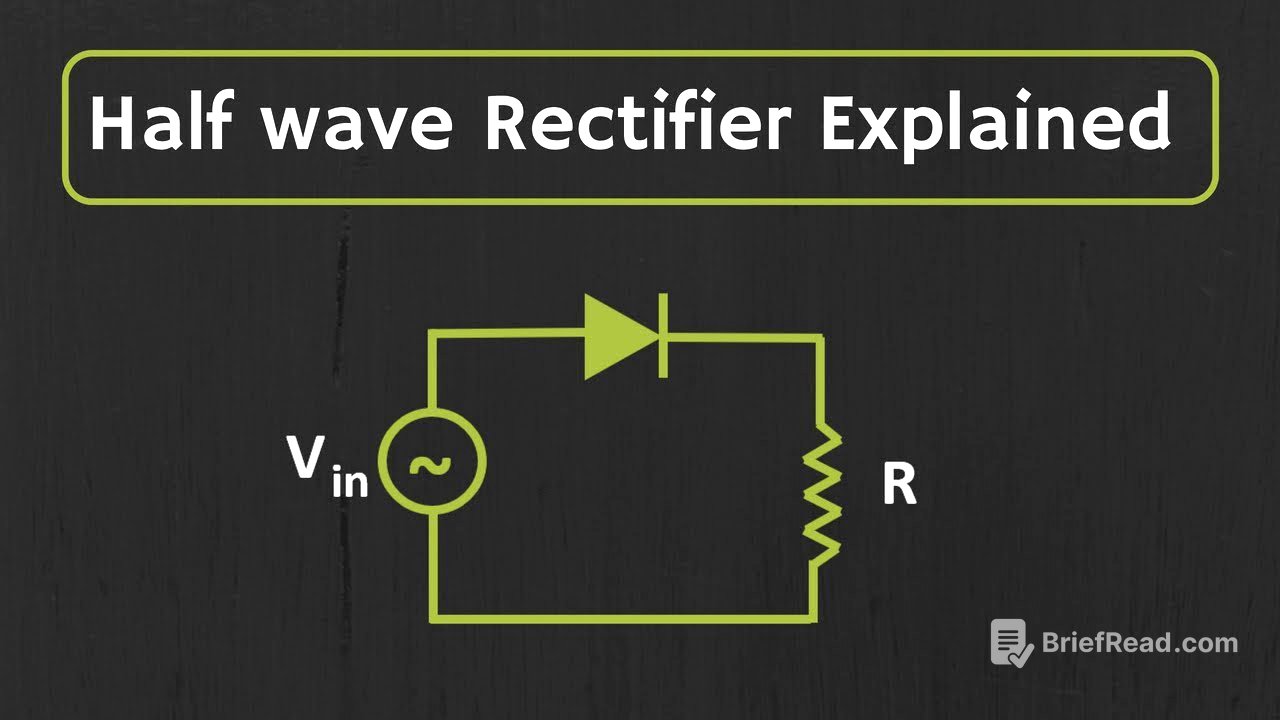
Half wave rectifier circuit and its working [1:00]
The half-wave rectifier circuit allows only one half of the sinusoidal input signal to pass through, blocking the other half. This converts the AC signal into a pulsating DC signal. The circuit consists of a diode connected in series with a load resistor. During the positive half-cycle, the diode is forward-biased and conducts, allowing the input voltage to appear across the load. During the negative half-cycle, the diode is reverse-biased and blocks the current, resulting in zero voltage across the load. If we consider the forward voltage drop of a silicon diode (0.7V), the diode conducts only when the input voltage exceeds 0.7V, reducing the peak output voltage to Vm - 0.7V. However, in many practical cases, the input voltage is much larger than the diode voltage drop, so the drop can be neglected.
Average value of half wave rectifier [4:54]
The average value of the half-wave rectifier output is calculated considering the waveform, which is Vmsin(wt) from 0 to T/2 and zero from T/2 to T. The average voltage is given by the formula 1/T integrated from 0 to T of v(t) dt. Substituting the waveform, the average voltage simplifies to 1/T integrated from 0 to T/2 of Vmsin(wt) dt. Solving this integral, the average value of the half-wave rectifier is found to be Vm/π.
RMS value of half wave rectifier [6:02]
The RMS (Root Mean Square) value for the half-wave rectifier is another important parameter. The general formula for RMS value is the square root of (1/T) integrated from 0 to T of V^2(t) dt. For a half-wave rectifier, substituting the value of v(t) and evaluating the integral, the RMS value comes out to be Vm/2. The video also mentions that when the diode is conducting, current flows through the circuit. The peak current is Vm/RL, and the average current is Im/π, which equals Vm/(π*RL).
Peak Inverse Voltage (PIV) for half wave rectifier [7:35]
Peak Inverse Voltage (PIV) is the maximum reverse voltage that appears across the diode during operation. For a half-wave rectifier, during the negative half-cycle, the maximum reverse voltage across the diode is -Vm. Therefore, the PIV for a half-wave rectifier is Vm. When selecting a diode for the rectifier, it's important to ensure that the diode's PIV rating is higher than the peak amplitude of the applied input voltage.
Ripple factor of half wave rectifier [8:23]
The ripple factor quantifies the amount of AC ripple present in the output DC voltage. It's defined as the ratio of the RMS value of the ripple to the average value of the output waveform. For a half-wave rectifier, the ripple factor is 1.21, indicating a significant amount of ripple in the output.
Half wave rectifier with capacitor filter [9:10]
To reduce the ripple in the output waveform, a capacitor filter can be added across the load resistor. During the positive half-cycle, the diode is forward-biased, and the capacitor charges up to the peak voltage Vm. Once the capacitor is charged, the diode becomes reverse-biased, and the capacitor discharges through the load resistor RL. Assuming the RC time constant is much larger than the time period of the waveform, the capacitor discharges linearly. When the input voltage becomes greater than the capacitor voltage again, the diode becomes forward-biased, and the capacitor recharges. This charging and discharging cycle results in a smoother output waveform with reduced ripple. The peak-to-peak ripple voltage can be approximated as Idc/(f*C), where Idc is the average current, f is the output frequency, and C is the filter capacitance.
The efficiency of the half wave rectifier [12:12]
The efficiency of a rectifier measures how effectively it converts AC input power into DC output power. For a half-wave rectifier, the efficiency is 40.6%, which means only 40.6% of the input power is converted into DC power. This relatively low efficiency is a limitation of the half-wave rectifier.
Applications of half wave rectifier [12:57]
One primary application of half-wave rectifiers is in AC to DC conversion, particularly in linear power supplies. The AC voltage is stepped down using a transformer, then rectified, filtered to reduce ripple, and regulated to provide a stable DC output. However, due to its poor efficiency and high ripple factor, half-wave rectifiers are rarely used in practical power supplies. Another application is in signal demodulation, where a half-wave rectifier can recover the envelope from a modulated signal.