
TLDR;
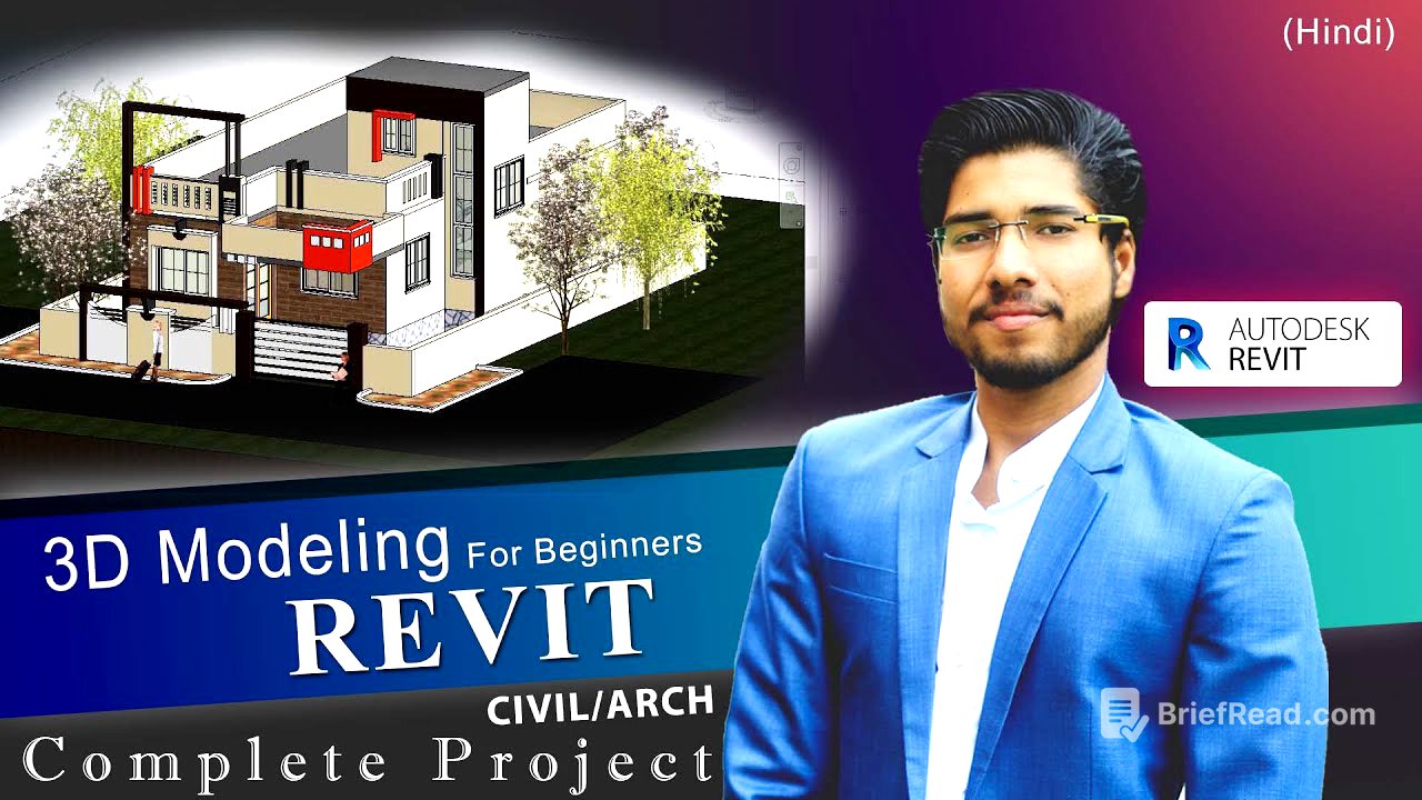
Alright ji, this video is a complete guide to creating a 3D bungalow model in Revit. You'll learn how to plan, extrude, and use various options to bring your design to life. The video covers setting up units, importing AutoCAD plans, creating walls, fitting doors and windows, adding staircases, and designing the exterior with cool stuff like a plinth, headroom, and porch. Plus, you'll get the hang of coloring and rendering your model to make it look super realistic.
- Learn to create a 3D bungalow model in Revit.
- Import CAD files, create walls, and add architectural elements.
- Design the exterior with plinths, headroom, and a porch.
- Color and render the model for a realistic look.
Introduction to Revit and Setting Up the Project [0:33]
The video starts with opening Revit and setting up a new project. It doesn't matter if you have an older version; you can still follow along. The presenter selects the architectural template for the project. If you can't find the templates, don't worry, there will be a video on how to add them later. Once the new page opens, the project browser and properties panel are set up on the side for easy access.
Checking and Setting Project Units [2:46]
Next up is checking and setting the project units. Press "UN" on your keyboard to open the project units panel. Here, you can set the units to meters or feet, whatever you like. For this 3D model, feet and fractional inches are used, so that's what's selected.
Understanding the Revit Interface [3:51]
The video explains the different tabs in Revit, focusing on the architectural tab for walls, doors, and windows. The properties panel lets you tweak the settings of these elements. In the project browser, you can find all your documents like floor plans, ceiling plans, elevations, and sheets. Double-click to open any of these.
Importing AutoCAD Plans into Revit [4:46]
Now, it's time to open the AutoCAD file of the bungalow plan. This file, which is 25 feet by 50 feet, will be imported into Revit as a reference for the 3D model. To import, go to the insert tab and click on "Import CAD." Find your CAD file, and before opening, make sure to adjust the settings. Change the colors to black and white, select inches as the unit, and set the position to "center to center" so the plan is placed right in the middle of your Revit view.
Creating Walls in Revit [8:53]
With the AutoCAD plan imported, it's time to create walls. First, measure the wall thicknesses using the "DI" command. The exterior walls are 9 inches, and the interior walls are 4.5 inches. Go to the architectural tab, click on "wall," and then edit the wall thickness. Since there's no 9-inch wall available, you'll need to edit a generic wall type. Duplicate the generic wall, rename it to "9-inch wall," and then change the thickness in the edit structure settings. Do the same for the 4.5-inch wall.
Setting Wall Height and Location Line [13:19]
After setting the wall thickness, set the height to level 2. This means the walls will automatically go up to level 2. If you change the level height later, the walls will adjust automatically. Choose the location line for drawing the wall. You can select "wall center line," "exterior," or "interior." The exterior point is used for this model. Use the space bar to flip the wall direction as you draw.
Adding Interior Walls and Doors [17:18]
Continue drawing the exterior and interior walls using the AutoCAD plan as a guide. Remember to leave spaces for doors. To add doors, go to the doors tab. Select a door size from the available templates. If you need more options, you can load families from the US imperial library. Choose a door and fit it into the wall, using the space bar to flip the direction.
Loading and Placing Doors [20:19]
To add different door designs, use the "load family" option. Go to the US imperial folder, then doors, and choose a residential door. You can select multiple sizes by holding control while clicking. Once loaded, you can place the new door just like the others.
Fitting Windows and Adjusting Visual Styles [22:33]
To fit windows, change the visual style to "wireframe" so you can see the windows in the AutoCAD plan. Measure the window sizes using the "DI" command. Then, go to the windows tab. If you need a sliding window, load it from the US imperial library. Select the sizes you need and place them in your model.
Loading Sliding Windows and Setting Dimensions [24:32]
To load a sliding window, go to load family, navigate to the windows folder in the US Imperial library, and select a double-panel sliding window. Choose the sizes you need, like 5 by 3 feet for the kitchen. You can also edit the window dimensions by selecting a type, clicking "edit type," and changing the width and height.
Placing Windows and Using Visual Styles [27:50]
Place the windows in the model by clicking on the walls. If the windows aren't visible, check your visual style settings. "Hidden line" will hide the windows, while "realistic" or "consistent colors" will show them.
Adding Ventilators and Adjusting Seal Height [29:32]
To add ventilators, you can use a double hunch-type window. Edit the type to change the size to 24 by 30 inches. Place the ventilators in the bathroom. You can also adjust the seal height of the windows in the properties panel.
Creating a Staircase [30:45]
Now, let's create a staircase. Go to the staircase option in the architectural tab. Choose a "cast in place" monolithic stair. Set the location line to the left side, the actual run width to 3 feet, the desired number of risers to 16, and the actual tread depth to 9 inches. Start drawing the staircase from the left side, creating eight risers, then a landing, and then the remaining risers. Finish the staircase and delete the railing on the wall side.
Adding a Plinth and Adjusting Levels [33:24]
To add a plinth, go to an elevation view. Adjust the levels so that level 1 is at 2 feet and level 2 is at 12 feet. Create a new level for the plinth at 0 feet. Rename the levels to "Ground Level," "Plinth Level," and "Slab Level."
Drawing the Plinth and Adding Entry Stairs [43:14]
Go to the plinth level and draw the plinth using the floor tool. Set the thickness to 2 feet. You can use the "pick walls" option to quickly create the plinth boundary. Trim any extra lines. To add entry stairs, go to the ground level and create a small staircase from the ground to the plinth level.
Creating a Slab and Headroom [47:57]
Go to the slab level and create a slab using the floor tool. Set the thickness to 6 inches. Create a shaft opening for the staircase. Then, go to the headroom level and create walls for the headroom. Add a floor to the headroom level.
Adding Windows to Headroom and Adjusting Walls [55:18]
Add windows to the headroom walls. Split the walls where you want to create openings. Detach the walls from the slab floor and attach them to the headroom level. Fit windows into the openings.
Creating a Porch and Parapet Wall [1:01:15]
Go to the slab floor and create a porch using the floor tool. Offset the porch slab downwards by 2 feet. Add a parapet wall around the roof. Draw the porch walls and adjust their base offset.
Adding Design Elements with Model In Place [1:11:52]
To add design elements like grooves and railings, use the "model in place" option. Select a category like "generic models" and use the extrusion tool to create your designs. Set the work plane to the surface where you want to draw.
Extrusion Techniques and Adding Details [1:15:52]
Use extrusion to create various design details on the bungalow. Set the work plane to the desired face and draw your shapes. Extrude the shapes to the desired thickness. Use void extrusion to remove material where needed.
Creating Gate and Compound Wall [1:37:48]
Create a compound wall around the property. Add a gate to the compound wall. Use extrusion to create the gate design.
Adding Footpath and Road [1:51:17]
Add a footpath around the bungalow. Use the fillet arc tool to round the corners of the footpath. Create a road using the floor tool.
Coloring the Model [1:55:03]
To color the model, switch to realistic visual style. Go to the modify tab and use the paint tool to apply colors to the walls, floors, and other elements. Create new materials in the manage tab if you need specific colors or textures.
Applying Paints and Materials [1:59:25]
Apply different paints to the walls, floors, and extrusion. Use the paint tool to select a material and click on the surface to apply it. You can also edit the material settings to change the color and texture.
Adding Grass and Tiles [2:12:16]
Apply grass material to the ground surface. Apply tile material to the porch and other areas.
Setting Up Camera Views [2:15:14]
To render the model, set up camera views. Go to the ground level and select the camera tool. Click to place the camera and adjust the view range.
Adjusting Graphic Display Options and Rendering [2:17:25]
Adjust the graphic display options to set the background. You can choose a sky, gradient, or image. To render the model, go to the view tab and select render. Choose a quality setting and render the image.
Rendering Settings and Exporting Images [2:21:17]
Adjust the rendering settings to control the brightness and exposure. Export the rendered image to your desktop. You can also add plants and other entourage elements to the model.